A Microstrip Dipole Antenna for Digital TV
Author: Diego Cuevas
Originally published: 11 June 2024
This project was made as part of the first Antennathlon competition organized by the Department of Telecommunications of the Electrical Engineering Division at UNAM’s School of Engineering. Event date: May 24th, 2024.
The project is based on the work of a team belonging to the Taiwan National University, in their paper “A small microstrip antenna for the digital television system by Bent Topology”. All credit on the idea goes to them.
Objectives
- Simulate and build a microstrip dipole antenna according to the specifications given by the original paper.
- Compare my results with the originals and analyze them.
- Test the antenna I built and ascertain it works to receive Digital TV signals.
Introduction
Antennas, in principle, are energy transducers that allow us to transmit and receive energy in the form of electromagnetic waves. Some of the most important characteristics of antennas, or at least the ones most important to understand this project, are:
- Impedance: In a way, it’s almost the same as the more widely known electrical resistance, impedance refers to the opposition any given electrical wave encounters while traveling through any medium.
- Standing Wave: When an EM wave crosses through a new, different medium, a reflection phenomenon occurs, where a reflected wave, carrying some of the energy of the original wave, travels back to where it came from, here the standing wave results from the sum of the original incident wave and the reflected wave.
- Reflection Coefficient: It refers to the energy carried by the reflected wave, the ideal value for this coefficient is below 14 decibels, and is sometimes represented by the symbol \(S_{11}\). The main reason why a high reflection coefficient appears, is due to an impedance mismatch between the transmission line and the antenna itself, both components must have similar impedance for the wave to travel through without reflecting energy.
- VSWR: The Voltage Standing Wave Ratio is the ratio between the max and minimum amplitudes of the standing wave, and it’s a quick way to see if the transmission line’s impedance matches the antenna’s, the closer to “1” the VSWR is, the better matched they are.
For this project, the VSWR is be the main indicator of how well optimized the antenna is, where the target is to have a VSWR value below 2.
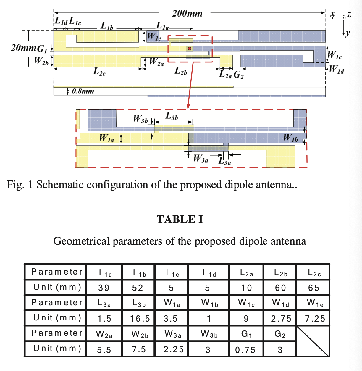
In this project, the main idea was to build a microstrip antenna where both sides of the PCB act as “poles”, thus making it a dipole, to reduce the size of the PCB required, the poles would be bent. The antenna was simulated and built according to the following specifications obtained from the original paper:
Simulation
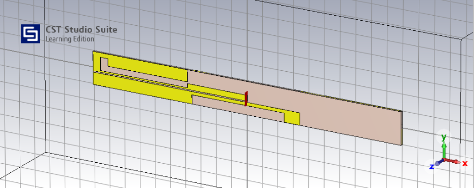
The software used to simulate this project was CST Studio Suite by Dassault Systèmes.
Important considerations:
- The original specifications required a PCB with a thickness of 0.8 mm, since it was pretty much impossible for me to find one like that, I used a 1.5 mm thick PCB, this might be important later on.
- I ran two simulations, considering two different waveguide port positions since the original paper doesn’t explicitly say where the coaxial cable is connected.
The 3D model made in CST Studio:
First simulation
For the first simulation, I placed the waveguide port directly at the edge of the PCB, close to the upper pole so that the physical connection with the coaxial cable could be done easily using a 50Ω SMA connector.
These were the results:
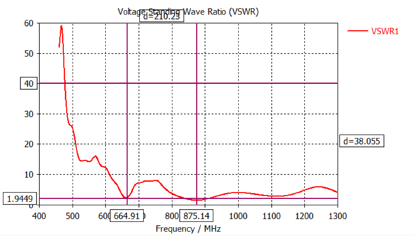
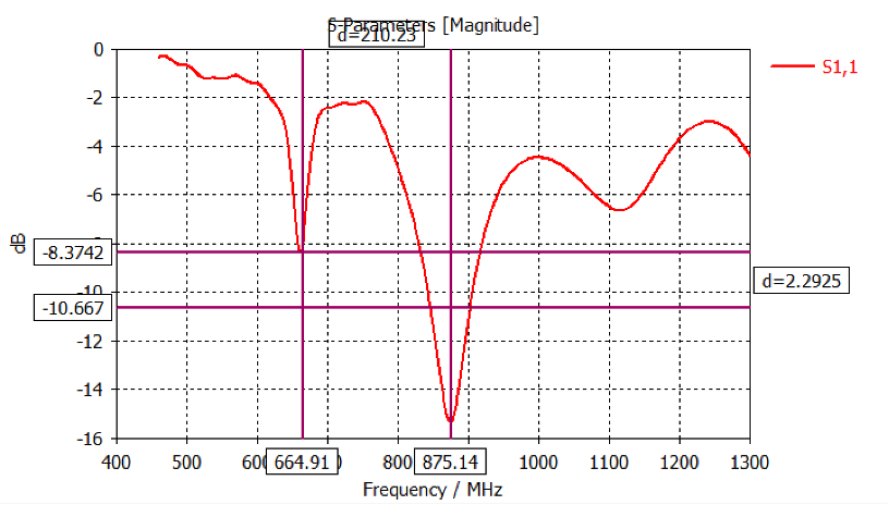
According to the simulation, the antenna was optimized for two main frequencies, 665 and 875 MHz, where the VSWR was below 2 and the \(S_{11}\) value was -8 and -15 dB respectively.
Second simulation
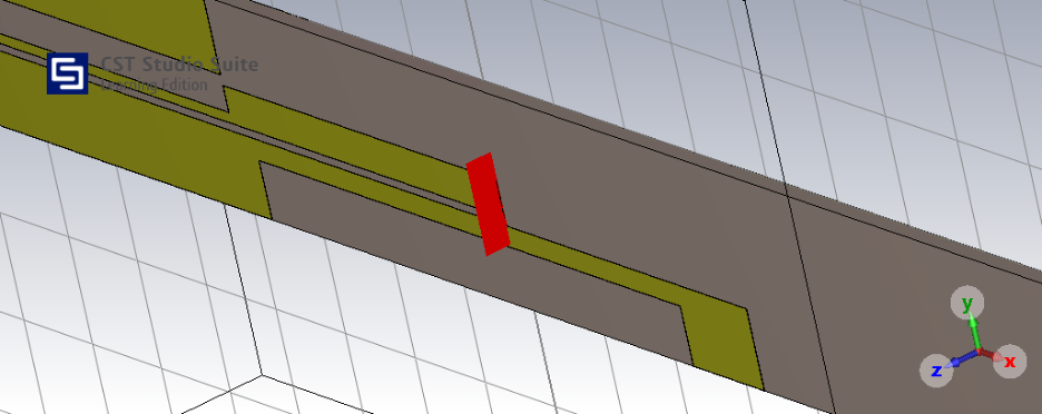
For the second simulation, I placed the waveguide port pretty much at the center of the PCB. where the main pole’s strip begins, as the original paper seems to indicate implicitly:
These were the results:
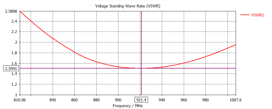
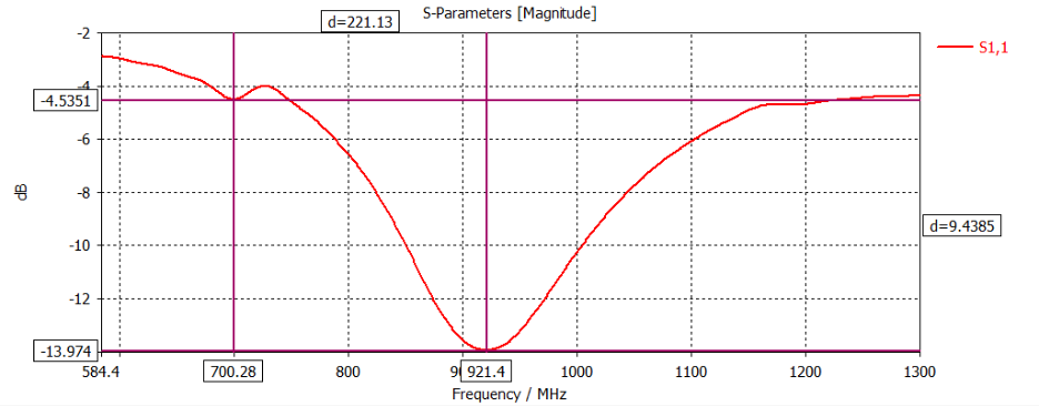
According to the simulation, the antenna was optimized for one main frequency at 921.4 MHz, where the VSWR was 1.5 and the \(S_{11}\) value was -14 dB.
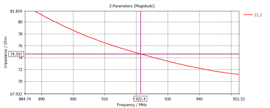
The simulation also revealed the antenna had a 75Ω characteristic impedance, this will be important for the construction process:
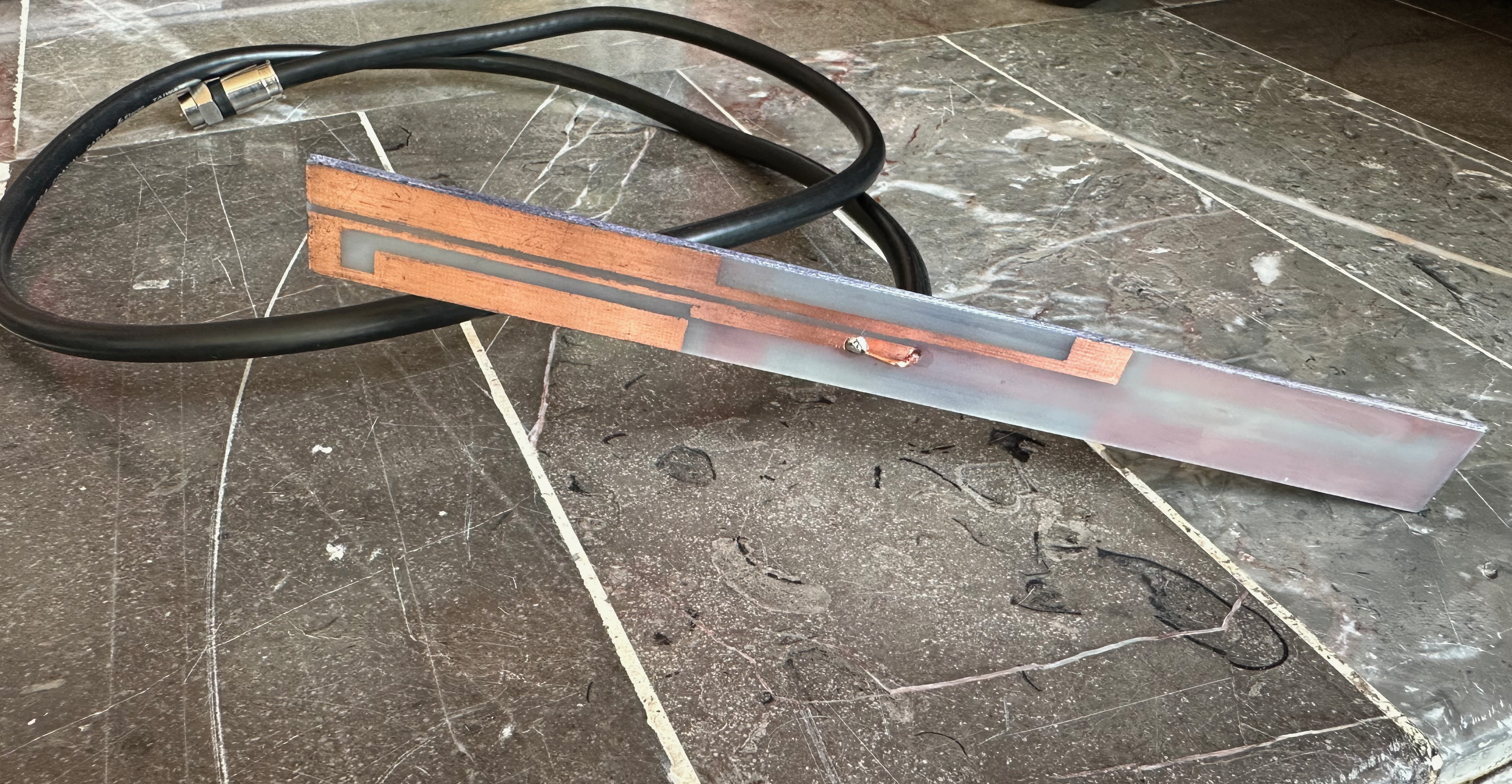
Physical antenna
Due to cosmetic reasons, I decided the best way to go about building the antenna was by following the second simulation’s concept and connect the coaxial cable in the middle of the PCB, by drilling a hole and connecting the cable to the poles’ feeding strips. Another important reason to go with this design was that the characteristic impedance of the antenna was 75Ω according to the simulation, so using an SMA connector would be less than ideal.
Construction steps:
- Use sandpaper to eliminate imperfections on both sides of the PCB.
- Cut PCB into a 20x2 cm piece.
- Draw the antenna pattern over the copper with a marker, such method was used because at the time of making this project, I did not know how to design and print PCB patterns via software, thus absolute precision was not possible.
- Submerge the piece into ferric chloride (taking proper precautions) for around 20 minutes or until all the copper has completely disappeared.
- Wash off the marker’s ink.
- Drill a hole through the piece right in the middle, big enough for a coaxial cable’s core to pass through.
- Solder the coaxial cable’s core and shield to each poles’ feeding strip.
Real-world Tests
Once the physical antenna was built, it was time to test it out. First, the \(S_{11}\), VSWR values were tested out using a Rhode & Schwarz Spectrum Analyzer FSH4:
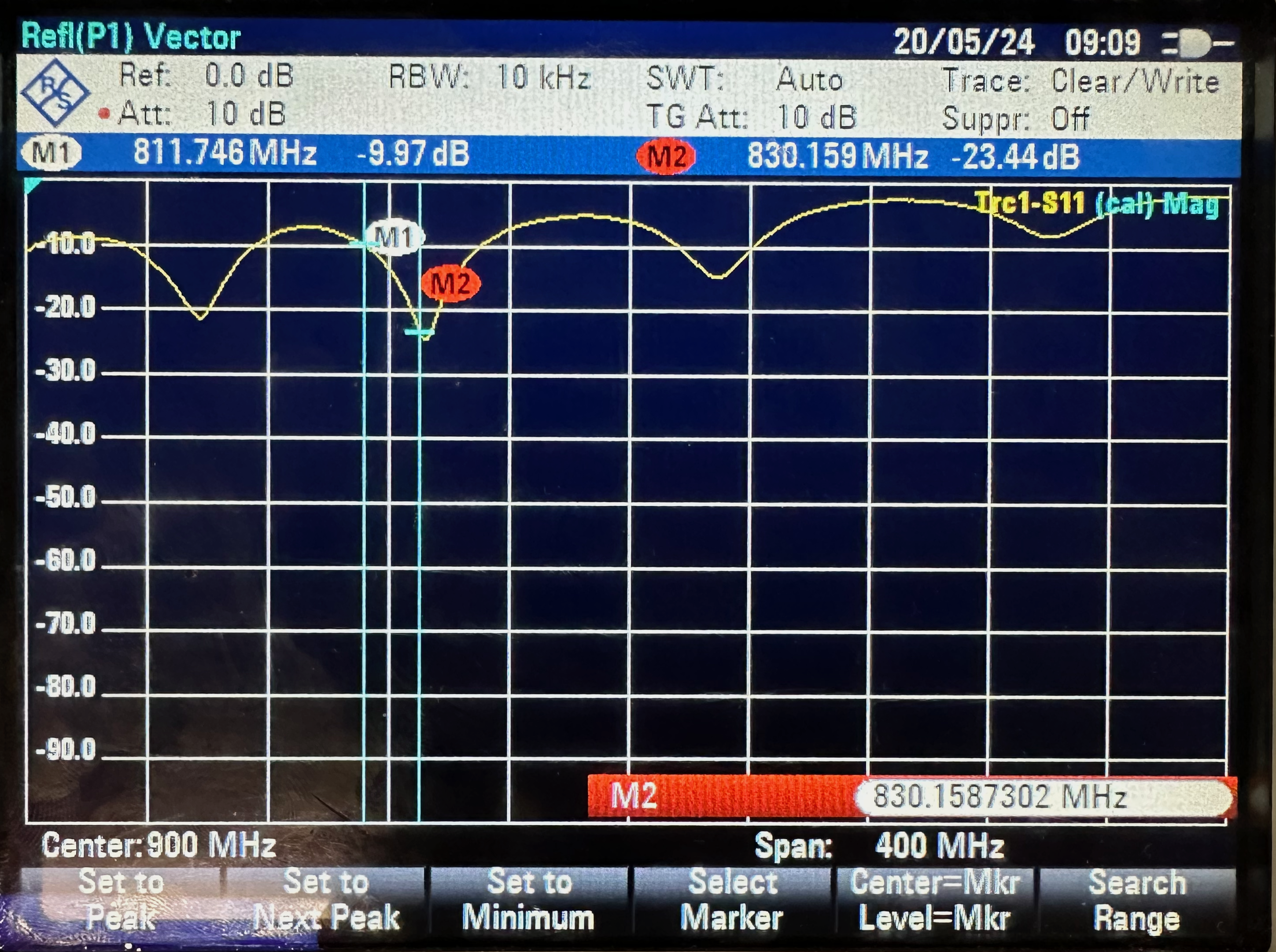
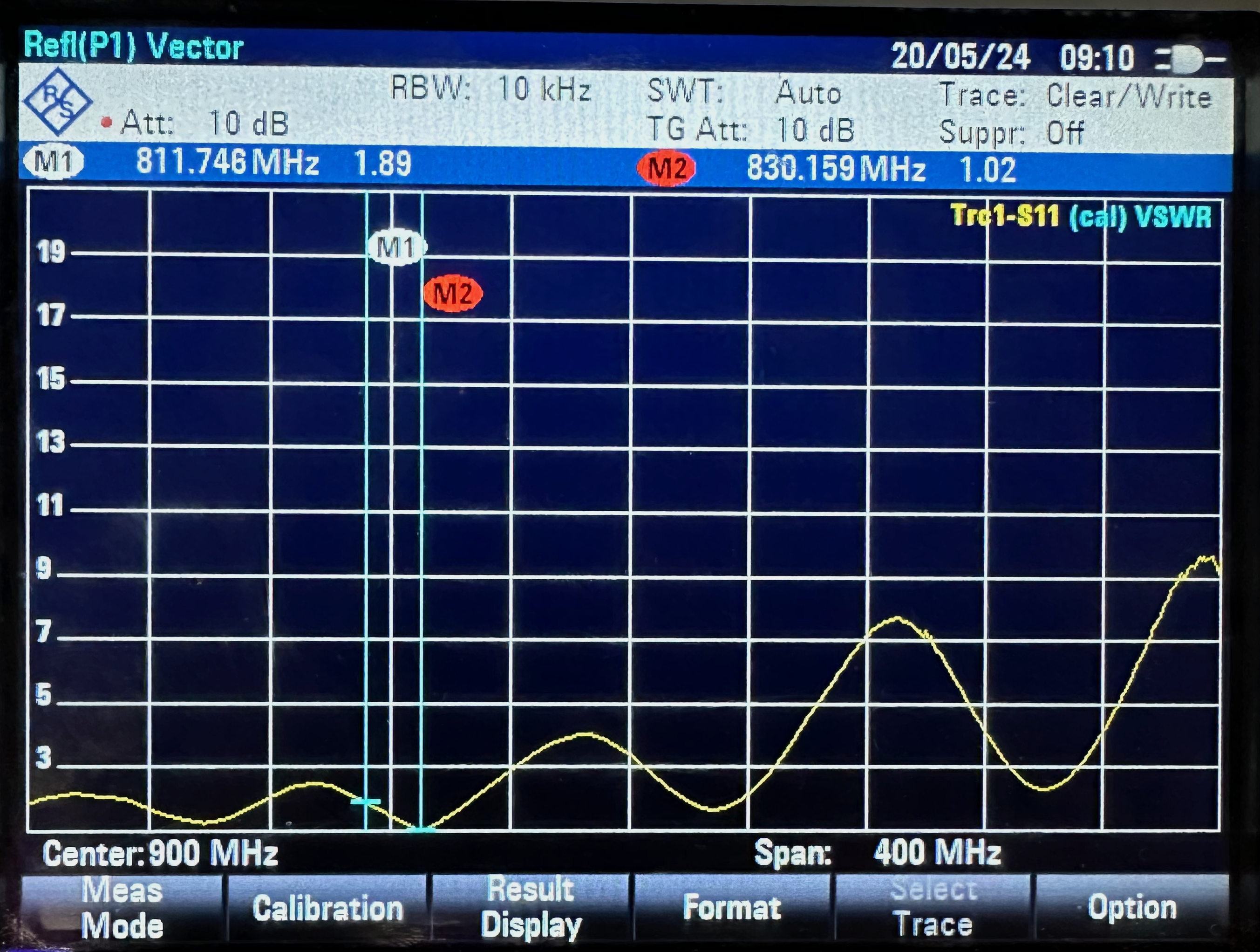
The actual built antenna was specially optimized for a frequency of 830 MHz, where \(S_{11}\) = -23.44 dB and it had a whopping 1.02 of VSWR.
As for the question of whether or not it actually worked for receiving TV signals, the answer is YES. Below is a video of the antenna in action:
Result Analysis
The obtained results were quite different to the originals.
Both the simulation and IRL tests yielded very different results, the original operating frequency of 750 MHz was completely displaced and even the computer simulation was off by around 100 MHz.
So what happened? Well, as stated from the beginning, a special consideration had to be done regarding the thickness of the PCB used, this small change is the main suspect of what went wrong. Other than that, despite my best efforts to draw the pattern as accurately as possible, that just wasn’t possible. It’s also worth noting that the simulation had a small detail, where it wasn’t quite possible to simulate the antenna as it was built, since the specific tool that would’ve allowed me to insert a cavity into the PCB to simulate a coaxial cable passing through was blocked due to the license type, so nothing could be done about that. Also the original paper states the simulations were done using Ansys’ HFFS software, so more differences.
Conclusions
This is the first hands-on project I’ve done that truly felt like real engineering. I learned a lot about how antennas work, how to use computer software to simulate their behavior and most importantly how to build one (the whole manual construction project was really cool), however, due to the fact this whole project was more about coping someone else’s process, I’m still left with the doubt of how the original team determined what measurements they used for the pattern and how could I try to make my own designs.
In the end, the most important thing is that the antenna works! But how can it visualize channels whose frequencies are so far from ~830 MHz, and with VSWR values above 50? Truth is modern TVs are built so they will be able to visualize a channel even if its frequency has a VSWR above 2, or 50 for that matter, so the antenna still works pretty good for practical purposes, even if the frequency for which it is optimized isn’t actually used by any channel in the Mexico City area.
As it can be seen in the IRL test YouTube Video, this antenna is now permanently connected to my bedroom’s TV for my personal use.